This topic provides additional information about the tool deformation models. Formulas are not provided here, as standard finite element analysis methods are used in the calculations. This section describes the calculation features applied in each model, their differences, as well as recommendations. The main information is provided in the Coupled deformation section.
Simulation of tools with interaction at a single step
In this model, the tool is considered absolutely rigid. The tool mesh is not deformed, however, the stress-strain fields, including displacements, are calculated and displayed. The simulation is performed at the post-processing stage. The method of recalculating nodal loads through distributed pressure is used for the computation. Contact between bodies, including the workpiece and the tools, is processed using the normal non-penetration condition. The simulation can be run using the button on the simulation control panel:
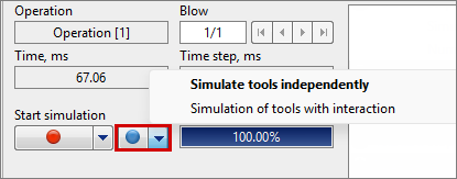
The results will be available only on one simulation record (one step):

|
Information |
The method of recalculating nodal loads through distributed pressure is based on converting the forces acting from the workpiece into distributed pressure, which is defined as the ratio of the force to the area surrounding the node and is then distributed linearly over the element, taking into account the shape functions. |
|
Independent tool simulation at a single step
Independent tool simulation differs in that contact between the tools is not taken into account. Each tool is calculated separately, using the method of converting nodal loads into distributed pressure.
Stressed state only
The calculation algorithm is similar to the Coupled tools simulation at a single step option, however, in this case, the results are recorded at every step. The method of recalculating nodal loads through distributed pressure is used for the calculation. Contact between bodies is processed using the normal non-penetration condition.
|
Information |
The Stressed state only model is recommended when tool deformation has little influence on the shape change of the workpiece. |
|
Separate
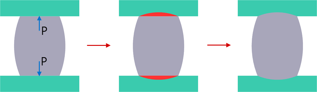
The simulation is performed at the post-processing stage, similar to the Stressed state only model, however, tool deformation is taken into account. The method of recalculating nodal loads through distributed pressure is used. Contact between bodies is processed using the normal non-penetration condition. The simulation of coupled deformation at each simulation step consists of three stages:
1.First, the workpiece is deformed by a rigid tool, and the forces acting from the workpiece on the tool are determined.
2.Then, the elastoplastic deformation of the tool is calculated under the action of the computed forces.
3.After that, the program adjusts the shape of the workpiece according to the obtained deformed shape of the tool.
Thus, the deformed shape of the tool is always “one step behind” the real process.
|
Information |
It is recommended for simple geometries without small fillet radii and with small deformations. It is not recommended for cases where tool displacements are comparable to the thickness of the workpiece. |
|
General
The general model takes into account the simultaneous simulation of the deformation of the workpiece and tool as interacting bodies, similar to the deformation analysis of two workpieces. Contact between the bodies is handled using the penalty method with special contact elements. A direct recalculation of nodal loads is applied for calculation. When using this model, it is important that the contact elements of the workpiece and the tool are similar in size.
|
Information |
It is recommended to apply this model when tool deformation has a significant influence on the shape change of the workpiece. |
|
Features of contact detection between tools
When using the Stressed state only or Separate deformation models, contact between tools is taken into account only if displacements in one of the tools occur as a result of workpiece deformation, and are not transferred from a driven motion.